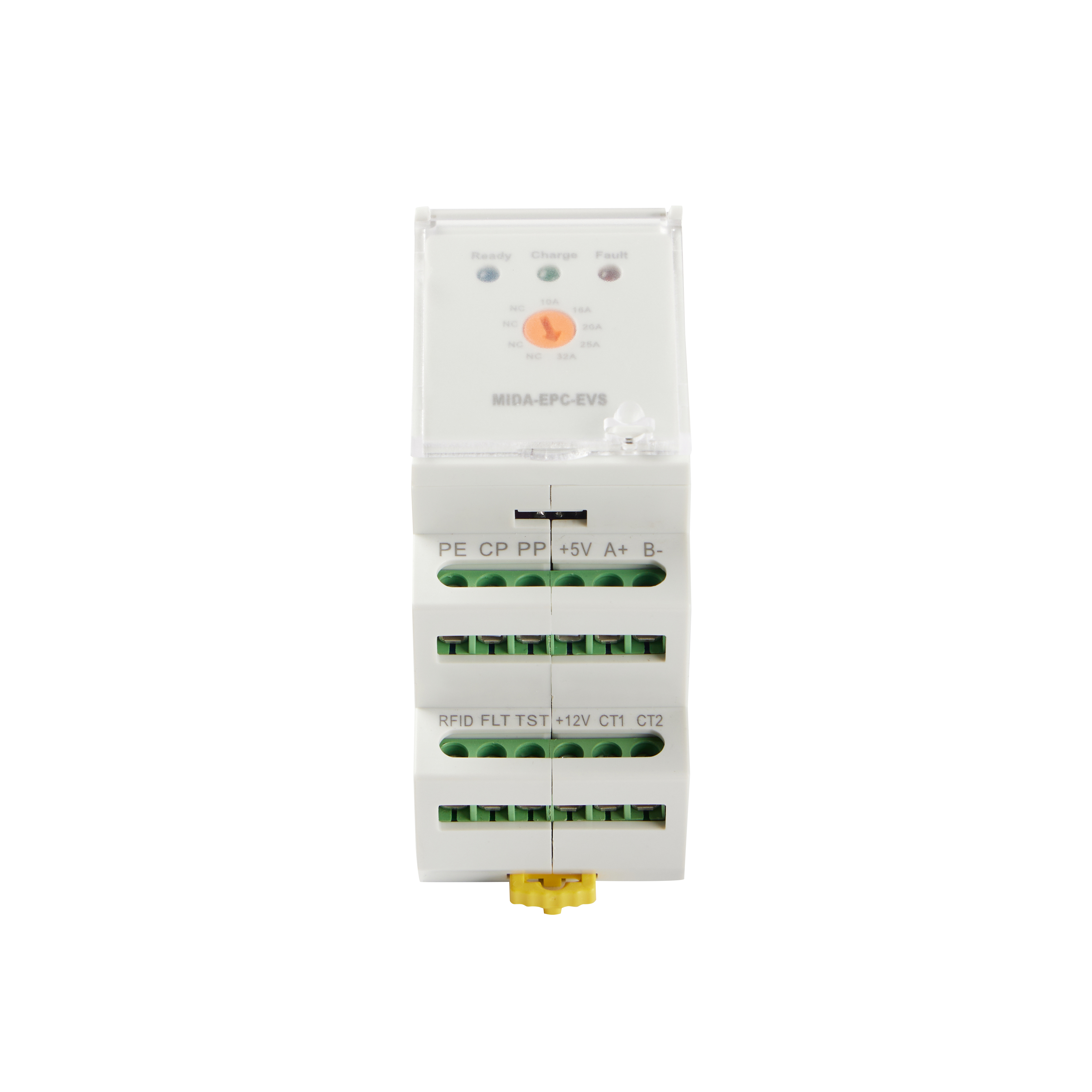
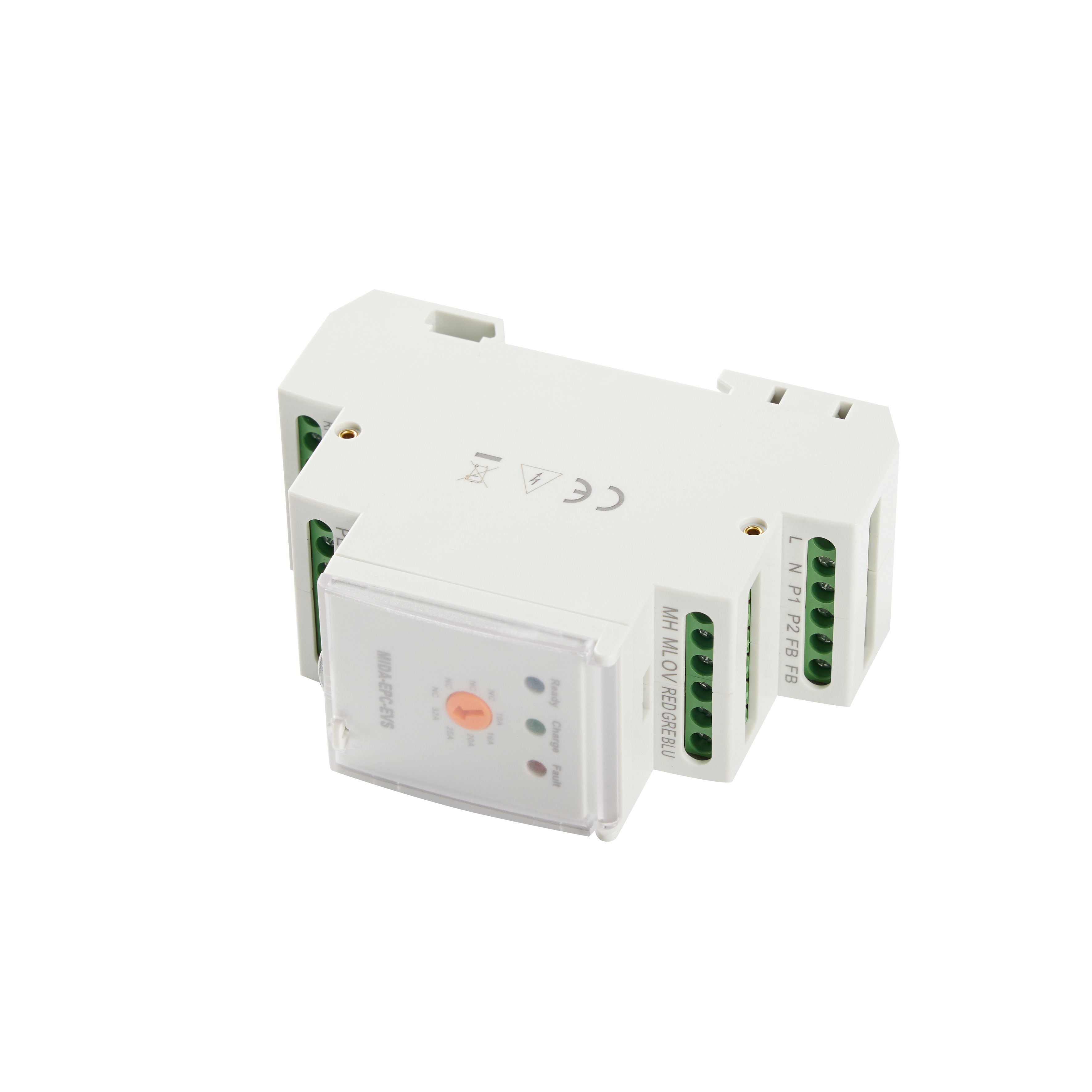
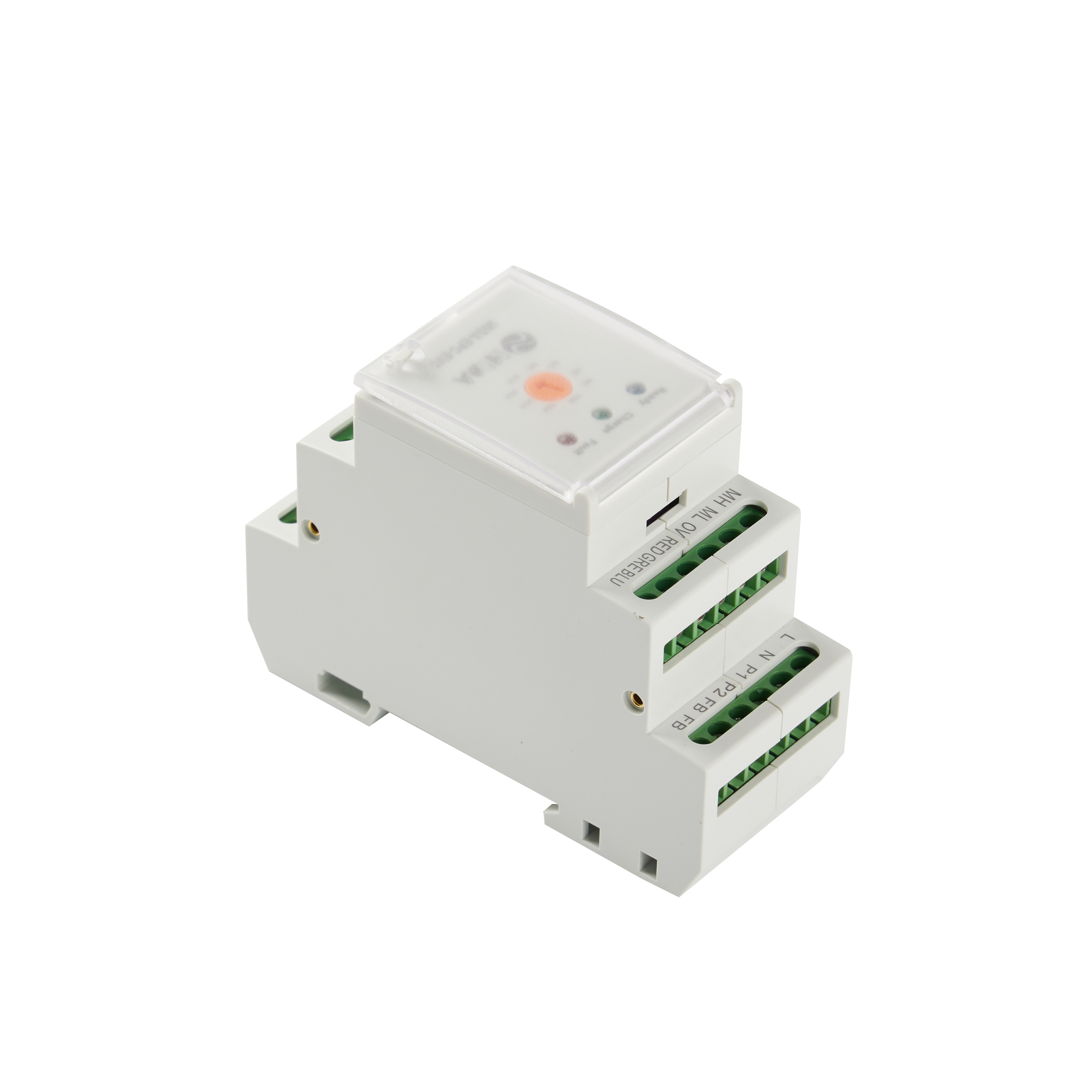
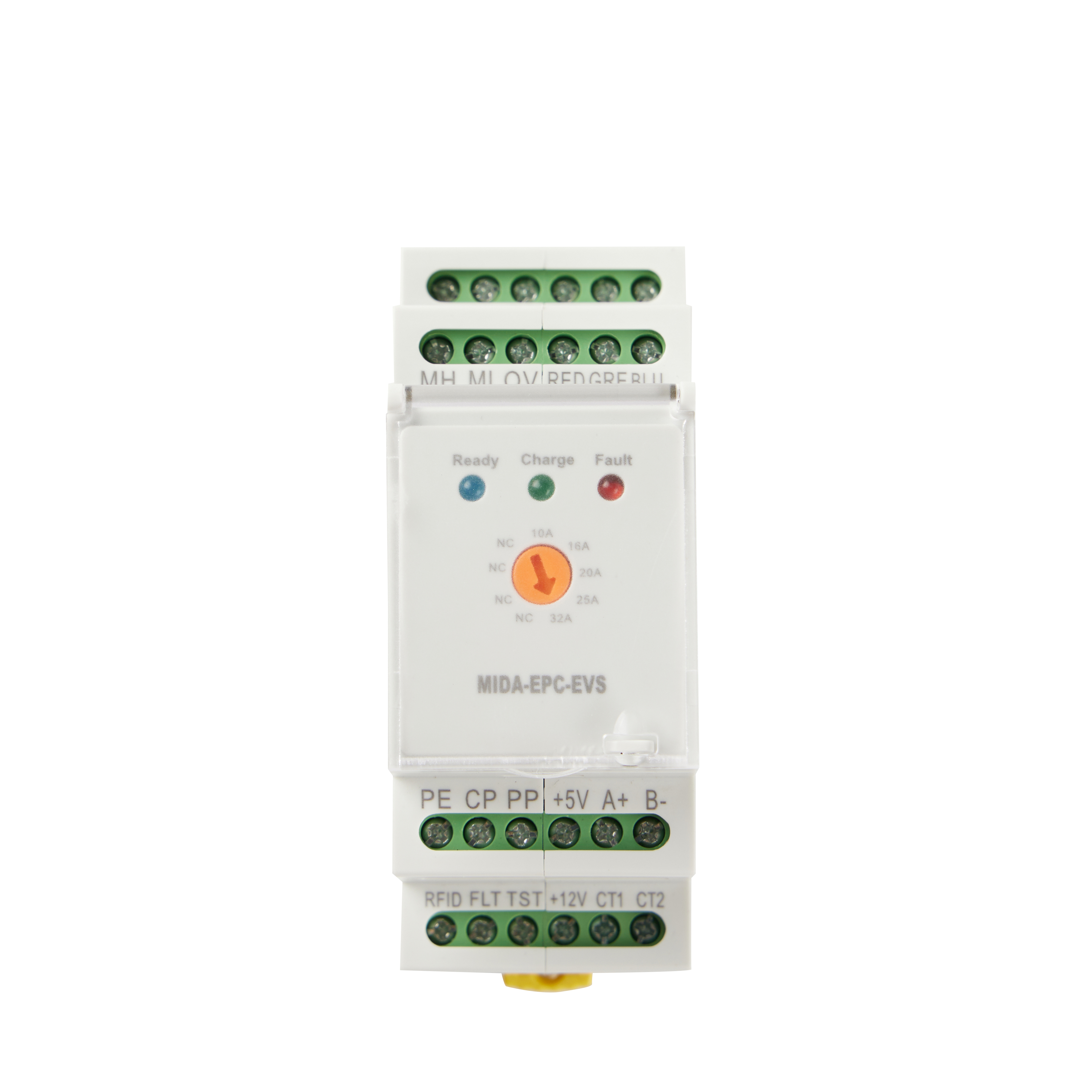
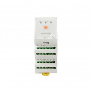
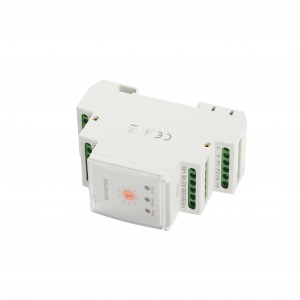
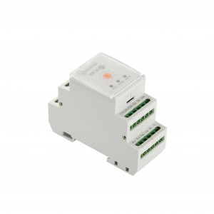
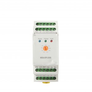
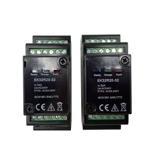
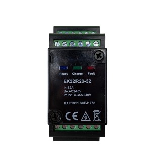
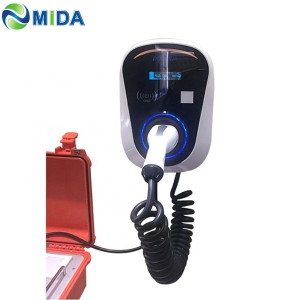
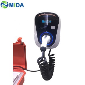
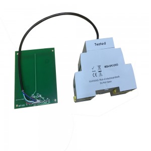
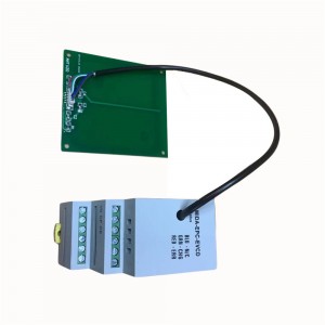
Product Name:32A EPC Electronic Protocol Controller EVSE
Maximun Charging Capacity Indication : 10A ,16A ,20A,25A,32A (Adjustable)
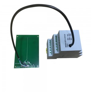
Product Model:Model:MIDA-EPC-EVCD( Cable Version with RFID)
L This is where the AC ‘live’ or ‘line connection is made (90-264V @ 50/60Hz AC)
N This is where the AC ‘neutral’ connection is made (90-264V @ 50/60 Hz AC)
P1 Relay 1 live from RCCB
P2 Reley 1 live from RCCB
GN For extemal L ED connection for green indication(5V 30mA)
BL For external LED connection for blue indication (5V 30mA)
RD For external L ED connation for red indication (5V 30mA)
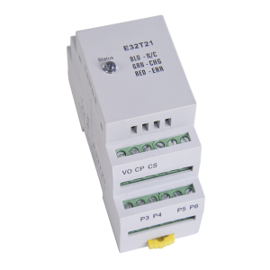
VO This is where the‘ground’ connoction is made
CP This connects to the CP connector on the IEC61851/J1772 EVSE connector
CS This connects to the PP connector on the IEC61851 EVSE connector
P5 Provides 12V continuously to energise solenoid for hatch lock
P6 This provides 12V 300mA for 500 ms to engage the lock for motorised lock
FB Reads lock feedback for motorised locks
12V Power: 12V
FA Fault
TE Test
Standard IEC 61851 , IEC 62321
EVSE Protocol Controller (EPC) is the intelligent part of the Charge charging stations. It is the communication to control the charging procedure of
electric vehicle ,and conforms to electric vehicle standard IEC61851 or SAEJ1772.Mounting onto standard rail according to DIN EN 60715
It is divided to cable version and socket version.
EVSE Protocol Controller
3.2 Function description
3.3.1 Charging process of controller with cable type (only CP signal is needed)
After switching on the working voltage, the module starts to initialize and perform the function self-test
(LED light flashes circularly), waiting for the car to connect. The controller waits for the charging cable to
connect to the vehicle (status a), and the LED flashes blue continuously. If the cable matching with the
controller has been connected (state B), the LED turns to stable blue light and turns on the electromagnetic
lock switch. After the gun head interlock, if the vehicle is in State C, the controller will make P1/ P2 in closed
state (connected state), and the LED will turn to stable green light. If status D (ventilation required) is displayed,
because the controller has no heat dissipation function, the controller makes P1 / P2 in the open state (off state)
and turns off the electromagnetic lock switch at the same time, the gun head interlock will be invalid, and the
controller will turn off the charging procedure, and the LED will turn into a stable red light.
Ventilation requirements
In the absence of ventilation, the risk of asphyxiation may be caused due to the accumulation of some battery
related gases when charging indoor. If the charging process is carried out indoor, forced ventilation shall be
installed, the charging pile controller does not have forced ventilation function.
Connection confirmation line (CS) current, resistance correspondence information.
current resistance/ current resistance/ current resistance / current resistance/ current resistance
32A 732Ω / 25A 536Ω / 20A 432Ω / 16A 348Ω / 10A 249Ω When the input resistance (minimum) is lower than 100Ω,
it cannot be charged or interlocked. The controller will reduce the current load to 7a within 5S, and the controller
will enter Status A until the resistance value of the input current rises.
Wiring instructions
Controller signal line P1: Blue 2.5 mm2
Controller signal line N : Blue 2.5 mm2
Contactor coiling opening and closing line N: Blue 2.5 mm2
Power output line N: Blue 4mm2
Continuous output line N: 2.5 mm2
Contactor coiling opening and closing line L: Brown 2.5 mm2
Controller signal line L : Brown 2.5 mm2
Continuous output line L: 2.5 mm2
Power output line L: 4 mm2
WAGO 1
WAGO 2
Curve B RCCB
Controller
Contactor
Terminal blocks
Input line
Input line of charging plug
Two colors signal grounding wire 2.5 mm2
Black signal wire 0.5 mm2
Brown outgoing line L: 6 mm2
Blue outgoing line N: 6 mm2
Two colors grounding wire: 6 mm2
